The integration of magnetically coupled technologies into integrated electronic circuitry can involve a number of undesired effects, caused by the generated and uncontrolled fields.
The objective of this experiment is to understand how the magnetic fields propagate in a Wireless Power system, which can be the effect of the uncontrolled fields and how they can be controlled with magnetic shielding.
For this purpose we will design and build a basic Wireless Power system, evaluate its efficiency with and without EMC countermeasures. We will also observe the effect of the eddy currents generated by a magnetic field crossing a conductive plane.
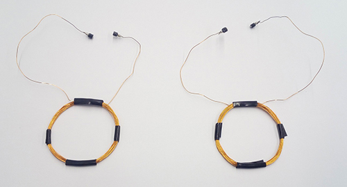
1. Magnet wire 26 – 30 AWG
2. 9V Battery
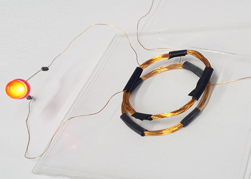
3. LED with VF = 2 V
4. Oscillator integrated circuit capable of providing a 100 kHz square signal (a suggested type is the DIP 8 pins LMC555).
5. N-channel Power MOSFET with IDS= 2 A and VGS= ±20 V (a suggested type is the IRF610PBF).
6. Passive components: Four resistors (470 Ω, 2 x 100 Ω and 5.6 kΩ), two capacitors (0.1 uF and 1 nF).
7. Oscilloscope
8. Conductive plane (i.e. Aluminum foil, PCB with ground plane…)
9. Magnetic shielding material (i.e. ferrite sheet)
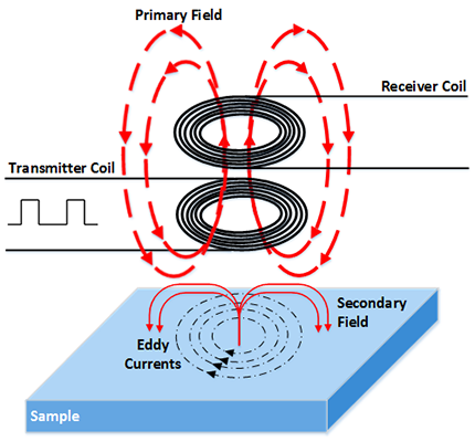
Inductive coupling works by creating an alternating magnetic field in a transmitter coil and converting that flux into an electrical current in the receiver coil. The alternating magnetic flux is generated by plugging an AC signal in the transmitter coil. This field is induced in the receiver coil producing a current in it transferring energy from the transmitter to the receiver through the air when the receiver is inside of the created electromagnetic field area.
The transfer efficiency can be improved with a higher coupling factor and with it is possible to reduce the losses. An inductive coupling system with a significant distance between the transmitter and receiver coils is defined as a loosely coupled system due to only a fraction of the transmitted flux is captured in the receiver.
Losses in this kind of communication can generate eddy currents (also known as Foucault currents). This effect consist of loops of electric current induced within conductors by a changing magnetic field in the conductor, due to Faraday’s law of induction.
The effect of eddy currents are intentionally used in induction heating systems in order to heat objects as for example in electric cookers in which the eddy currents flowing through the resistance of the material going up its temperature by Joule heating
An oscillator circuit based on the 555 device and a MOSFET transistor are used in order to generate pulses and step up the voltage in the transmitter coil. It generates a changing magnetic field in the transmitter coil that is induced in the receiver coil as explained above.
The 555 oscillator IC is powered by 9V battery and its external components have been chosen to generate a 100 kHz square signal which controls the transistor gate terminal.
Thus, as a result of the magnetic coupling theory, if a LED is connected between the two terminals in the receiver, it switches on when it is placed over the transmitter coil.
Thus, as a result of the magnetic coupling theory, if a LED is connected between the two terminals in the receiver, it switches on when it is placed over the transmitter coil. here.